Haywired on the bench, circa 1995, Minneapolis
Today's package
|
Overview
|
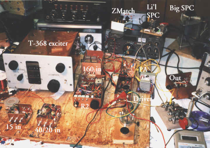
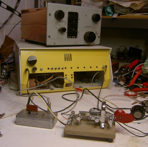
A constant work-in-progress... my approach to using the marvelous single-signal direct-conversion R2 receiver design in a multiband, modular amateur station. In the top photo, you see how it was laid out, and used, for several years. Yes, a little haywire, but quite functional. The boxes are made from double-sided PC board material. The BNC jacks are a special PC board type that I found cheap at my local surplus house. They mount with 4 ground pins and a center conductor pin, saving space. Around January 1, 2001, the driver, PA, and R2 went into a large flea-market cabinet with a hinged lid, so it looks neater and yet can still be shown off and easily fiddled with. Microphonics and other glitches are much reduced with a setup like this. The T2 exciter is in there too, but still not hooked up (it's the nicest-looking board, though...) The digital age is dawning with a Hands DDS3 VFO coming my way; will this go in the cabinet or in a separate unit for a variety of uses? Decisions, decisions. See below for some possible upgrade directions. |
| The old
modular layout |
 Interconnections
were a combination
of Molex
connectors,
BNC's, clip leads, etc. Interconnections
were a combination
of Molex
connectors,
BNC's, clip leads, etc.
The modification of the
surplus Collins T-368
exciter
is a separately
documented
project in itself! This unit was available from Fair Radio Sales in
the early to mid 90's for about $45; many correspondents tell me this
source
has dried up. The basic PTO is 1.5-3 MHz, with multipliers to 3-6,
6-12,
and 12-24 MHz with a mechanical digital dial. Once transistorized, it
is
the most stable analog VFO I have ever used, mostly because it is built
so heavily. Others may wish to use various combinations of homebrew
VFO's,
multipliers, or pre-mixers, especially for portable use! I
started out with boxes that combined input
filtering
and phase shifting. BNC connectors on both the input module and
the
R2 were on 3/4 inch center to center spacing, with a set of
male-to-male
BNC adapters remaining "resident" on the R2. I switched filters and
phasing
networks with one 4PDT slide switch. Rick's suggested "pi" phasing
network
in the R2 article is easy to deal with, tuned up predictably, and
worked
well. I think, though, with the haywired approach, there was more RF
radiation
than I might have wanted. I got by, but hum started to show up on the
high
bands (LO leaks out to an AC power line, gets modulated, and re-enters
the radio). Microphonics and not-perfectly-noiseless connections also
showed
up, but usually was tolerable. The photo below gives you an idea.
<> The input filters are
standard 2-resonator
bandpass filters
found in various homebrew books. They're adapted to tune a range, using
dual 250 pF plastic variables (Mouser Electronics). |
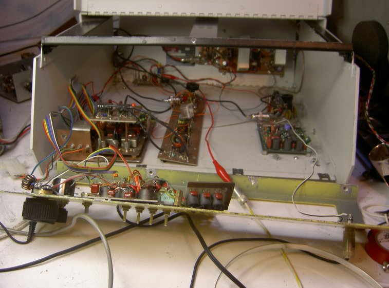
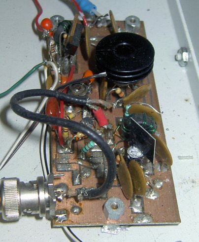
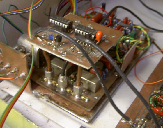 The "front end" and audio amp of this board date back to
my first effort at the "iron-on toner transfer" method of PC board
etching - barely enough copper left, but it works! The original audio
quadrature section was cut out and replaced with Glen
Leinweber's circuit from the R2a. The circuit board on top
contains 2 74HC240 CMOS buffers to
generate square wave drive - a good idea in
theory, but in practice a bit unstable, so they're now bypassed. Note
the cool construction, though - semi-rigid .141" hardline soldered to
the board, and SMA connectors! The "front end" and audio amp of this board date back to
my first effort at the "iron-on toner transfer" method of PC board
etching - barely enough copper left, but it works! The original audio
quadrature section was cut out and replaced with Glen
Leinweber's circuit from the R2a. The circuit board on top
contains 2 74HC240 CMOS buffers to
generate square wave drive - a good idea in
theory, but in practice a bit unstable, so they're now bypassed. Note
the cool construction, though - semi-rigid .141" hardline soldered to
the board, and SMA connectors!Rick's R1 article has some precautions for power connections. Because of the high gain on one board, any circulating ground currents generated by the output stage must be minimized. Therefore you don't just connect the DC negative lead to any old point on the chassis, but right to the point where the output transistors are grounded. If you go him one better, and return the SPEAKER ground lead to this point also, you get even more immunity to feedback. This means to insulate your output jack from chassis ground (easy with PC board boxes: simply scrape some copper away). In my new cabinet setup, I chose to keep the R2 board completely insulated from the chassis, making it possible to experiment with various grounding options to see if it makes any difference. Call it overkill, but I found some high-level
mixers at a
hamfest, the
SRA-1H (+17 dBm LO drive, I think), and have used them for some time. I don't have any preamps or front-end filters in there right now, trusting in my transmatch and transmitter lowpass filters to reject birdies. Eventually I'll get them all switched in somehow. You usually can get by without the preamp up to 20 meters, though 20 meters can use it sometimes. I find no need for it on 40 meters and below. When I've used preamps, these are what I've tried: 1) Mini-Circuits MAR-6 MMIC amp -- 3dB noise figure, 20 dB gain, 1 MHz-2 GHz bandwidth. It works well, but that's a lot of gain, and its output 1 dB compression point is only 2.5 dBm. But if you really want to listen down to the noise on a quiet band, or need something that at least gets you a start on VHF premplification, it's great. A little kit is available: the WBA-6 ($19.95) from Electronic Rainbow in Indianapolis.
My amplitude balance pot is put on the front panel, because readjustment is required for each band. You will most often get adequate rejection of the opposite sideband with a reset from memory. Best adjustment requires a steady carrier or VERY strong signal. Your phasing networks should only need to be adjusted once, unless you change your LO drive in some way. See this modification list for information on small
tweaks in the filter designs specified. Another important mod: The capacitor in the mute
circuit should be
reduced to
.03 uF if you want fast recovery for full break in CW. The 0.1 uF
originally
specified means a good half-second recovery time - far from adequate
for a CW man!
Switching out the highpass filter is another possible option. At first I did it with some trace cutting on the original board. With the changes made when the "R2a" circuit was added, it made me think about playing around with some highpass filtering as well. So I now have a 3-pole highpass filter , the inductors being wound on the ferrite potcores Glen refers to in his writings. It's set to roll off about 500 Hz to narrow the CW bandpass, and for voice modes it's just bypassed. Audio switching, pots, and filtering are precariously hung onto the front panel as displayed in the photo!
|
|
| You
need plenty of LO power to drive the
diode mixers
and overcome the loss in the splitters. The original mixers need +7 dBm
minimum, and I have even gone with SRA-1H mixers (+17 dBm drive!). So
once
you split it for transmit and receive (3 dB loss), and then again for
phasing
(another -3 dB), you need to make up that loss with higher output from
your buffer.. The mixers generate harmonics, and even prefer a square
wave,
so don't bother with the low-pass filtering featured in some buffer
designs.
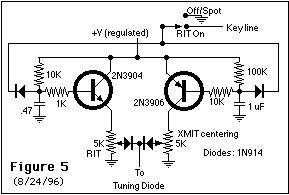
Any VFO you use needs a
varicap for CW and/or
RIT offset.
See the Lewallen Optimized QRP Transceiver (1994 ARRL Handbook, QRP
Classics)
for a good basic circuit. I implemented it this way in my T-368 exciter: Pick the capacitor for the right RIT range for your needs. Mine had to be big because the PTO operates at 1.5-3 MHz. Also be creative on your varicap diode. The NTE612 is designed as a varicap. But many diodes will work as varicaps. Lewallen suggested a zener diode. Try some old rectifier diodes in your junk box -- something that is likely to have a larger PN junction than a fast switching diode. Lewallen's RIT switching
is also OK as far as
it goes.
However, you can get offset above and below your frequency just like
the
big rigs with this circuit. Pick the capacitors for the right delay for your needs. Remember that when you unkey, the VFO needs to stay at the transmit frequency long enough for the PA output to decay. The RIT pot is on your
front panel, of course.
Pamper
yourself and use a 10-turn pot -- you won't regret it. The transmit
centering
can be an internal trimpot, or a front panel control. If you wish, add
resistors on either end of the pot(s) to limit the tuning to the most
linear
part of the varicap's range. The SPDT switch removes RIT by keying the
circuit. On CW, you would turn off RIT (switch to ground) to spot an
incoming
signal to zero beat, then turn on the RIT and adjust the RIT pot for
your
preferred beat note. (With experience and an ear for pitch, you don't
need
to do this every time). On SSB, of course, you normally tune with RIT
off,
and turn it on only as needed. Remember also that the diodes at the
output
will be part of your VFO thermal stability concerns. As temperature
increases,
the forward voltage drop goes down, thus the voltage increases, and
your
VFO frequency will creep up. To some degree this compensates for the
way
the varactor diode behaves: it creates a frequency drop with increasing
temperature (increasing capacitance). A very interesting document on the fine points on tuning diode temperature compensation, is the old Motorola bulletin AN847 - with today's fancy synthesizers it's marked as an "archive" document, but us conservative hams still using varicap diodes can still benefit from it. |
|
| The
standard homebrew/QRP books give you
plenty of circuit
specifics here. Typically, your keying circuits use a positive voltage
that is pulled to ground to transmit.
In my first iteration, blocked out above, I started with some driver gain blocks, and the final based on the "10-watt linear amplifier" (2 NTE236's) described by W1FB in the QRP books, with a more elaborate bias regulator. Funny, that PA never
worked quite right. But
eventually,
I found my way to the circuit's roots: Motorola's
classic old
application note AN779.
Turns out Doug's circuit was the second half of this. I built it up in
my own haywire fashion, and it gave out a good 15 watts... but was
never
quite stable. Then after a few years of using this, I hit on the
ingenious
and unique idea of using the board layout provided in the app note -
and
it worked flawlessly! Lesson: good layout does the trick, and if
somebody's done the work for you, don't re-invent the wheel. So here it
is: 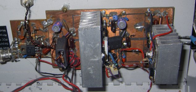
This is driven by a single 2N5109 linear stage (right). The board at the right includes another little 2N5179 driver, used earlier when more gain was needed - it's bypassed now. TR SWITCH.... That's on the small board attached to the left of the PA. This is a broadband circuit, needing 20 to 40 mA of total diode current. I went as high as 60 mA to eliminate bleed through from a 50 kW AM broadcaster 5 miles away, thus the paralleled 330 ohm resistors. 330 ohms, 1/4 watt may be sufficient for many needs.The DC switching part is cobbled from some circuit I read somewhere, and modified. The IRF510 MOSFET is used for its high gate impedance and sharp switching characteristic, otherwise the capacitor (.47 uF) that holds the switch closed on key-up has to be outlandishly large. There are probably smaller MOSFETs available for such low-current switching, but this one you can get at your local Radio Shack. The RF switch itself is
drawn
from the Ten Tec
Argosy, and
handles that rig's 50 watts with ease. 1N4007's are 1 kV rectifier
diodes
that have a PIN structure; they operate satisfactorily, though they are
not rated for RF PIN service. The 1N914's rectify the transmitted RF to
back bias the diodes on transmit. At 5 watts, I have alsof had
satisfactory
results with 1N914's in the switching path; in this case you do not
need
the back-biasing circuit, because the fast switching diodes rectify
their
own back bias! I don't use the output transistor now, but I may try it
to cure some receiver audio pops at high volume levels. The chokes are
small molded ones at this power level; actually, the one on the
transmit
end could be eliminated if your DC return path is through an output
transformer
winding. 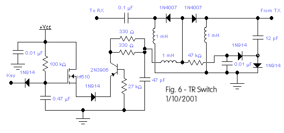 |
|
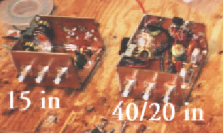
| Transmitter Filter Output Module | This is just a box with switch-selected lowpass filters of standard 50 ohm design for the various bands. |
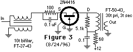 2) A
2N4416 grounded-gate stage (fig. 3). I can't remember where I read
these
specs, but I believe it has about 4 dB noise figure, higher overload
margin,
and a more manageable 10 dB gain. A better choice for HF, though I
found
the gain at the high end rolled off (maybe I need a better-selected
transistor...)
2) A
2N4416 grounded-gate stage (fig. 3). I can't remember where I read
these
specs, but I believe it has about 4 dB noise figure, higher overload
margin,
and a more manageable 10 dB gain. A better choice for HF, though I
found
the gain at the high end rolled off (maybe I need a better-selected
transistor...) 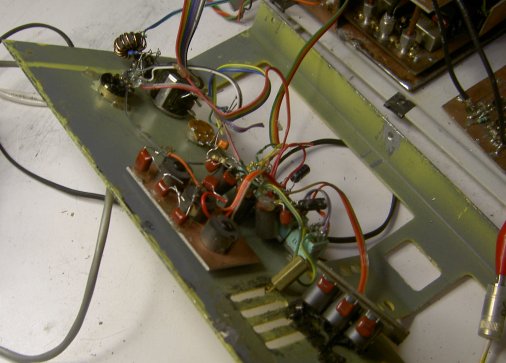 I have switching for a CW
and SSB lowpass
filter -- and
can switch them both out! It's an interesting hi-fi sound to hear
signals
above 3 kHz. My ears hear to 10 kHz or greater in my hi-fi headphones,
serving as a mini spectrum analyzer. Strong shortwave broadcasters
sound
stunning this way. At high gain settings, though, you may get some
oscillation,
sometimes supersonic.
I have switching for a CW
and SSB lowpass
filter -- and
can switch them both out! It's an interesting hi-fi sound to hear
signals
above 3 kHz. My ears hear to 10 kHz or greater in my hi-fi headphones,
serving as a mini spectrum analyzer. Strong shortwave broadcasters
sound
stunning this way. At high gain settings, though, you may get some
oscillation,
sometimes supersonic. 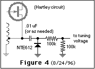
 It's a nice little 20 watt
amp design - 2
MRF476 drivers,
and 2 MRF475 output devices, both in push-pull. (These devices are no
longer
made, so I used the NTE235 and NTE236.) I found the biasing a bit
problematic,
wasting a ton of current to heat a resistor through a diode, and even
letting
the transistors go into thermal runaway! So I provided some adjustable
bias via pass transistors for both stages, based on the Ten Tec Argosy
once again. (All that stuff is slapped onto the heat sinks, which are
MUCH bigger than the small black metallic items specified in the
original.)
It's a nice little 20 watt
amp design - 2
MRF476 drivers,
and 2 MRF475 output devices, both in push-pull. (These devices are no
longer
made, so I used the NTE235 and NTE236.) I found the biasing a bit
problematic,
wasting a ton of current to heat a resistor through a diode, and even
letting
the transistors go into thermal runaway! So I provided some adjustable
bias via pass transistors for both stages, based on the Ten Tec Argosy
once again. (All that stuff is slapped onto the heat sinks, which are
MUCH bigger than the small black metallic items specified in the
original.)
| My T2
exciter board is now built, and mounted
in my cabinet,
but not yet in use. Rick's suggestions for station integration are made
with VHF mountaintopping in mind. What other possibilities are there?
This is yet to be determined... One bottom line: a separate transmit
phasing network (forget trying to share them on receive and transmit,
according to the original article - too many variables) One brainstorm... I would make everything switchable to get every mode possible, even if only just to say you can do it! Q INVERT would invert the audio phase (with a unity gain opamp inverter) coming into the channel that feeds the 90 degree mixer. (I think this will work -- engineers?) IDISABLE and QDISABLE would break the audio inputs at X and Y on Rick's schematic -- or possibly at the input of the audio phase shift network. CARRIER INSERT would ground the key line, unbalancing the mixer that receives in-phase LO energy. (See switching circuits below.) Here then would be your
modes (check me,
engineers!)
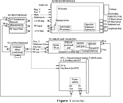
Below are proposed board interconnections. Only the DC control lines are shown; RF connections should be obvious. 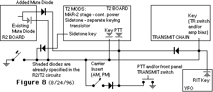 |
||||||||||||||||||||||||||
| Rick
Campbell, KK7B, “High-Performance
Direct-Conversion
Receivers”, QST, August 1992 (“R1”) Campbell, “High-Performance, Single-Signal Direct-Conversion Receivers”, QST, January 1993 (“R2”) Mouser Electronics, 2401 Highway 287 North, Mansfield, TX 76063-4827, tel. 1-800-346-6873 Fair Radio Sales Co., PO Box 1105, 1016 E. Eureka St., Lima, OH 45802 tel 419-223-2196 Doug Demaw, W1FB, “A Diode-Switched Band-Pass Filter”, QST, January 1991 Wes Hayward, W7ZOI, and Doug DeMaw, W1FB, “Solid State Design for the Radio Amateur”, ARRL Doug DeMaw, W1FB, “W1FB’s Design Notebook”, ARRL Motorola Documentation Library Motorola Literature Distribution Center - includes the archived old stuff Freescale Semiconductor (was Motorola Semiconductor) - List of RF design application notes |
||||||||||||||||||||||||||
|
||||||||||||||||||||||||||
|
The Author
|
 John
Seboldt, K0JD, began hamming as WN0QXG in about 1967. Music,
electronics,
and ham radio grew side by side in his youth, leading to work in the
broadcast
industry while studying music at Luther College, Decorah, IA, and The
University
of Iowa, Iowa City. Church music has been his main field -- he served
15 years
in the Twin Cities, and moved to Milwaukee in 1999. (Check out samples
of his music work at churchmusic.seboldt.net).
For now, technology has again claimed his working hours: at Time Warner Cable he's a
Broadband Technician, having worked in the cable industry since 2001. John
Seboldt, K0JD, began hamming as WN0QXG in about 1967. Music,
electronics,
and ham radio grew side by side in his youth, leading to work in the
broadcast
industry while studying music at Luther College, Decorah, IA, and The
University
of Iowa, Iowa City. Church music has been his main field -- he served
15 years
in the Twin Cities, and moved to Milwaukee in 1999. (Check out samples
of his music work at churchmusic.seboldt.net).
For now, technology has again claimed his working hours: at Time Warner Cable he's a
Broadband Technician, having worked in the cable industry since 2001.
E-mail me at k0jd at seboldt dot net (note spamfoil format - retype as standard address :-) ) |