| In April 1995 QST, Lew Smith wrote up "A Remote-Oscillator High-Frequency
VFO" whose buffer used a 74HC240 high-speed CMOS octal inverting buffer.
For any rig using diode mixers, square waves are ideal, so why not get
your LO power efficiently? This is now part of the T-368 VFO described
in other files as the frequency-determining heart of my R2/T2 station.
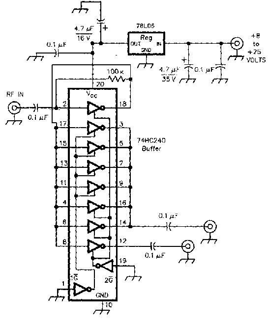
My adaptation of this circuit is as follows:
The main group of logic inverters is paralleled for substantial output capacity (but a rather low output impedance, on the order of a few ohms). The other can be used to output to another buffer, or for other light loads like a counter. The 100K resistor apparently biases the inverter to work with less-than-ideal 5 volt square wave input, such as from a VFO. This input seems to be a high impedance - high enough that you should put a 50 ohm resistor across it if that's important to your driving load. If input is lost, the system self-oscillates and draws destructive currents. So the 78L05 low-power regulator limits current to 100 mA when this happens. This idea comes from Rick Campbell, who used a similar approach with a 74AC04 hex inverter to generate square waves for a VHF multiplier in the LM2 "little mother board". This gives you approximately a 5 volt peak-to-peak square wave. If a sine wave had this p-p value, it would be 17.96 dBm, or 62.5 mW -- plenty to drive a pair of diode mixers after a splitter reduces it by 3 dB. The duty cycle looks close to 50 percent. Note that if you use the HCT chips available from Radio Shack, this will not be the case -- I got about 70% duty cycle with these. The driving impedance is lower than 50 ohms, which you need to be aware of when driving phasing networks for the R2. I did directly drive my phasing networks from one of these buffers for a time, which meant substantially higher values of inductance and capacitance than the rules of thumb called for, but it did work. I imagine a series resistor could provide the proper driving impedance - with some loss of output, of course. When applied to a conventional VFO, you may want at least one conventional buffer ahead of this. Lew used another 74HC240 -- with only ONE of its inverters with the 100K resistor from input to output -- as a buffer ahead of a stage similar to the above. In this case, the 100K resistor was not present in the final buffer. Another chip you can use is the 7404 series of hex buffers. In my R2, I'm now using a pair of 74HC04's at 5 volts, and have tried a faster 74AC04 as well. These buffers isolate the phasing networks from the diode ring mixers, providing a constant load (re-defined at 50 ohms by a resistor across the input). Need more power? Just jack up the voltage! These chips can run at higher voltages despite the ratings, but be careful.. In Feb. 1993 QST, Jacob Mahkinson used an HC flipflop running at 9 volts to generate hotter LO drive for a fancy DMOS FET mixer. In my VFO buffer, I've run mine safely at about 7 volts (a sine wave of equivalent p-p voltage would be 20.8 dBm) to drive a pair of SRA-1H mixers (requiring 17 dBm drive each) via a passive phasing network (3 dB loss). An adjustable regulator with a trimpot will make it possible to change your mind frequently. Probably the larger size of the 74HC240 is an advantage for heat dissipation if you're pushing the limits this way. In preparation for re-doing my phasing networks for the R2, I've discovered that at 7 volts, the output impedance is 4 ohms! (Quick and dirty measurement method: find the load resistor value that drops the no-load voltage to half. Voila, that value is your source impedance!) No wonder I had to use such large values in my phasing networks! Probably smart to add some series resistance to make it look like 50 ohms to whatever you're feeding it into. The auxiliary output drives another chip for totally isolated transmit buffering. Now it drives my drivers via a pot. Eventually this will drive the T2 exciter, whose conventional SBL-1 mixers (+7 dBm drive) will surely cry out for the merciful ministrations of an attenuator, lest they surely die from overdrive. |
