|
RF phase shift network
options
for the R2/T2 are many and varied. Here
is my favorite, and an elegant setup to bandswitch a group of them..
The
Twisted-Wire Quadrature
Hybrid
For more information and
applications for this slick little circuit:
see Reed Fisher (W2CQH), "Twisted-Wire Quadrature Hybrid Directional
Couplers", QST,
January 1978 (thanks to Eric, KC6SPN, for digging this up for me!)
It has a wide
bandwidth, small
number of components, takes care of splitting
AND quadrature in one fell swoop. And, you can bandswitch by just
opening
and closing the A, B, and C ports onto common busses, making
bandswitching
relatively easy.
(In-phase is the +45
port,
quadrature or -90 degrees is the -45 port.)
Assuming all ports are
at 50
ohms,
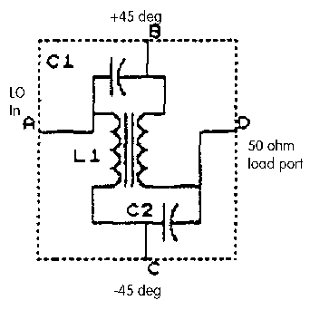
VARIATION 1, as
detailed in
the schematic:
L1: bifilar twisted pair on toroid, reactance 50 ohms at center
frequency.
C1, C2: 100 ohms reactance each at center frequency
Port D: terminate in a 50 ohm resistor.
You obviously have to
calculate your values from the reactance/frequency
formulas found in your ARRL Handbook or other references.
VARIATION 2 - above,
but
eliminate C2, and make your C1 twice the value
(i.e., 50 ohms reactance at the chosen frequency). This is what I'm
using
lately to save variable capacitors!
This gives you 90
degree phase
shift over a broad range. However, the
amplitude ratio between the two outputs will vary as you depart from
the
design frequency. No big deal - just tweak your amplitude balance pot
on
the R2.
In addition, for a
perfect
null, I make the capacitance adjustable with
tiny 1/4 inch trimmer caps I found at a hamfest.
Now, in the real world,
not
everything is 50 ohms; and for various reasons,
the audio phase shift networks in the R2 and T2 are not exactly 90
degrees,
either. So things may depart from the theoretical. Some reasons and
solutions after the next section...
The
"Quadrature Expressway" to switch several networks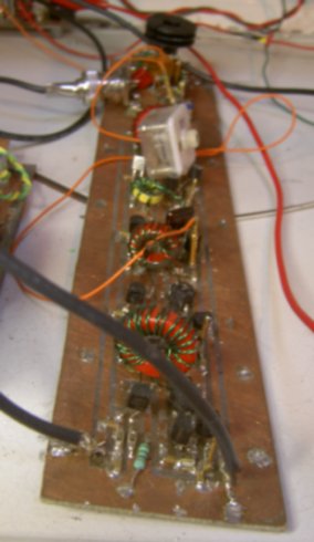
I decided to start
upgrading my old "plug-in module"
arrangement.
For the phasing network, I came up with a "three-lane microstrip"
board,
one microstrip each for LO in, in-phase out, and quadrature out. The
microstrips
are about 1/16 inch wide, in the top foil of the double sided board,
forming
an approximately 50 ohm transmission line with the bottom ground plane
foil. Then pads are provided for five of the above phasing networks,
plus
PIN diode switches. The extra pads near the microstrips probably
disturb
the perfect transmission-line characteristics, but it still works fine
at HF, and is cleaner than my old haywire setup for sure.
Components are a mix of
surface-mount and leaded components. Don't shy
away from surface mount - with a little care, a good magnifier, and
some
silver-bearing solder (even Radio Shack has the silver solder now),
it's
a compact and flexible way to do homebrewing. Paralleling components to
improvise the right value is a matter of just stacking your chips! (And
I don't mean at the casino...) A hamfest purchase of a whole reel of
3.9k
resistors, plus little packs of 500 chip capacitors (180 pF and .1 uF),
a kit of assorted NP0 chip caps from DigiKey, and miscellaneous other
hamfest
purchases make it possible to come up with the necessary values.
The LO input goes through an attenuating pot, then a 2N5109 amplifier
stage (not shown on schematic), to provide a uniform source impedance
and
adequate drive power. This feeds the center microstrip.
The networks do their
thing,
then send their signals to the outer microstrips.
A single PIN diode in each of the A, B, and C legs of each network
makes
or breaks the connections to the microstrips. I use the MPN3700, but
the
lower-voltage MPN3404 would do fine. (These are former Motorola parts,
now made by ON Semiconductor, and available from Allied Electronics).
Forward
bias on the diodes (about 6 mA each) switches them on, and isolation is
good enough for this application (about 40 dB at HF) by simply removing
the bias. (Reverse bias would increase the isolation, but is probably
overkill
except for more critical applications like front-end filter switching.)
I did, just for fun,
try
garden-variety 1N4148 diodes in one network.
With the values above, there was definitely an audible loss, so I
didn't
research it further. My guess is they'd need a lot more forward current
to turn them on better. Even if that helped when "on," I don't know if
the isolation would be adequate when "off." It's probably worth
shelling
out your shekels for the real thing.
Why did I have to
mess around so much with the theoretical values for a perfect null?
I've had Glen
Leinweber's R2a writings for some time, waiting for the right time
to implement the ideas or pieces of them. He makes his audio phase
shift
network tweakable, and provides a simple
schematic of an accurate audio quadrature generator to adjust it
right
on the nose.
In addition, I started
playing
with PSpice (as provided in the free
OrCad Lite v. 9.2 from Cadence Design Systems - see my simulation
primer), modelling everything in sight to find out the whys and
wherefores
of how things work, what happens if I tweak "widget X", etc. In
modelling,
I found (with perfect parts) that:
- the network behaved very
well, with a precise
90-degree phase difference
between the output ports over a wide frequency range
- changing the source or load
impedances changed only
the amplitude, not
the relative phases, of the outputs of the above network.
- changing only one or the
other of inductance or
capacitance, however, led
to changes in the phases from the theoretical 90 degrees, that varied
with
frequency.
This led me to the
conclusion that there must be some phase errors in my
audio phase shift network - precisely what Glen was addressing with his
adjustable (and lower-noise) network.
I built up his audio
quadrature generator, in preparation for building
the R2a phasing network... and thought maybe I should check my current
implementation of the original R2 network. Sure enough - over the
communications
audio band, there was quite a bit of audible difference in rejection,
sometimes
quite good, sometimes not so good. And, of course, the typical CW
listening
tone of 750 Hz was one of those not-so-perfect points!
So, clearly, I had been
working hard to get a perfect null at that frequency,
tweaking networks, adding capacitors, switching coil windings, and on
and
on... little knowing that my pursuit of the perfect null led to
compromises
in the total picture - like good null over the audio bandpass, and
closer-to-perfect
nulling over a wider RF tuning range.
Now I've finally built
part of Glen's
R2a: the tweakable
audio phase shift network. After adjusting it precisely with a
quadrature audio generator made from CMOS chips, any tweaking of the RF
phase shift network is fairly minimal. Nice!
|