| Simulation Software | It's all over the place in the technological realm - complete
communications
systems from concept to PC board can be tweaked pretty far just on the
computer screen.
ARRL recognized this a few years ago, and persuaded a major vendor of RF simulation software (Compact Software) to make a "lite" version of an industrial simulator, and release it as "ARRL Radio Designer". Trouble is, it was limited to the cumbersome text-entry style known as a "netlist". The scoop on this is at http://www2.arrl.org/ard/ . A series of QST articles ran on the use of this software, all available at that site, with netlist files included. (Those files can be opened, with some modifications needed, in Serenade referred to below.) Fortunately, one of its progeny is available free! Compact Software was acquired by Ansoft, and now marketed the Serenade package. Its free student version was Serenade SV, which I played with a bit. It seems to have been superseded by http://www.ansoft.com/ansoftdesignersv/ - give it a try. But wait, there's MORE out there for free! SPICE (in various
flavors)
is a standard of the industry for general simulation. Lots of older
versions
of SPICE are floating around on the net. I even have an old Mac version
that doesn't quite adhere to the Mac interface, but worked for me.
Orcad, www.orcad.com, seems to provide the best free versions. I used
Orcad 9.2 Lite Edition on a free CD from them, and now OrCad 10 is
available via a very large download, www.orcad.com
... Just to round out the picture, I'll mention the other major
simulator
for the education market, Electronics Workbench, from www.interactiv.com.
I have an earlier student version of this software, which cost about
$75
as part of a certification training package. It is a lot easier to use,
and runs more like a breadboard and test bench, with virtual test
instruments
like an oscilloscope and volt/amp meters, and switches that change
state
when you hit the space bar. The newest version, Multisim 2001, has a
free
demo, but with a 25-part limit and no save capabilities. Student and
personal
editions aren't too expensive, as quality software goes. It's surely
worth
a try if you want to spend some money.
|
| An OrCad Schematic | To start out, I modelled the keying waveforms
of one
of my RF driver stages, and it came out pretty close to what I have
actually
achieved over the years. Since I haven't downloaded all the parts
models
yet, I'm temporarily using another RF transistor in the model than what
I'm actually using (a 2N5109).
 Now this schematic for modelling has a few things added you wouldn't see in the construction schematic - the DC and AC voltage sources, and the source and load resistors, for example. Most notably, the little keying pulse generator inside the dashed box simulates a keydown-to-ground output from a key or keyer for a bunch of fast dits. (If there's a better way to do this, please e-mail me, somebody!) Once you draw that schematic in Capture, you set up simulation
profiles.
The "transient" analysis is basically an oscilloscope display - time
vs.
amplitude. This one is a 100 millisecond run - and it takes a while,
because
you're viewing the overall RF pulse shape of a keyed CW waveform. To
save
some time, I made the signal source only 100 kHz - otherwise it will
take
forever. As it is, the actual output file is 88 megs for this measly
100
milliseconds of simulated circuit operation, and took about 5 minutes
to
run on my P3-600. Then you place the "markers", the little colored
scope
probes you see above. And voilà:
|
| PSpice A/D Output from the Above | Here's the scope-like output of the "probe"
function of
PSpice A/D Lite. The yellow trace is the keying generator output; the
red
trace is the shaped DC voltage to run the amp; and the green waveform
is
the shaped RF output of the amplifier. I went for a fast but clickless
rise and fall time for my QRP CW work - about 1 ms rise, and 2 ms fall.
You could of course shape this according to taste by the values of C5,
R7, and R8.
|
|
|
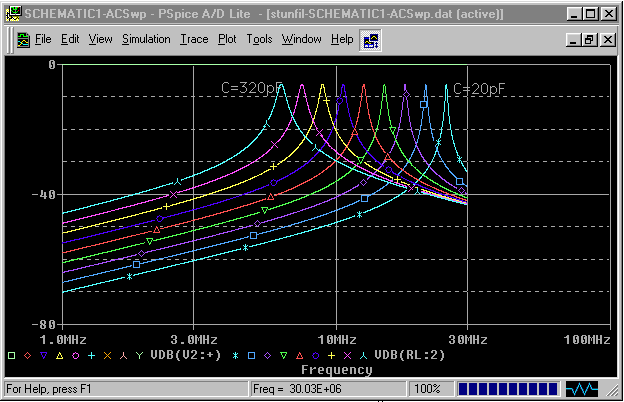
Tuned filter networks, like input bandpass filters for
receivers, are
fun to tweak on-screen for various combinations of bandwidth and
frequency.
I've always looked for good compromises in my fitlers when tuned over a
band of frequencies.
One interesting discovery I made was in the behavior of a
series-tuned
circuit operating at low impedance with a step-down transformer (50
ohms
to about 5 ohms). Its behavior is yet to be verified with real
components,
but this circuit:
Over the tuning range, the bandwidth of the filter (in terms of MHz/kHz) stays remarkably uniform. Transformers are 20:1 impedance range (about 4:1 turns ratio); L is 2uH; and in this example C tunes from 20 to 320 pF. We'll see how this works in real life... |


