Good old Doug DeMaw, W1FB (rest his
recently departed soul!) came up with the "SPC" antenna tuner a while
back,
in response (apparently) to the "Ultimate Transmatch" that had been
circulating
for a while before that. The version I'm reading from my 1988 handbook
claims better matching range with the same value components.
All I know is it has worked well for me in two versions. Both are
operated
as "pseudo-balanced" -- that is, a balun placed BEFORE the tuner
circuit.
It seems to work better with the balun than without, though the gurus
like
W7EL say lately (in some postings on rec.radio.amateur.homebrew) that
this
is not a true balanced situation. More arguments below on this.
Basic schematic from my ancient 1988 ARRL Handbook (except I add the
balun at the input):
                   C2b
  +------||--+--+---||---
  |      C1  B  |
Balun        B  = C2a      ant
  |       L1 B  |
  +----------+--+--------
The nominal values from the article are: C1, 200 pF; C2, 200 pF per
section;
L1, 28 microhenries, roller inductor.
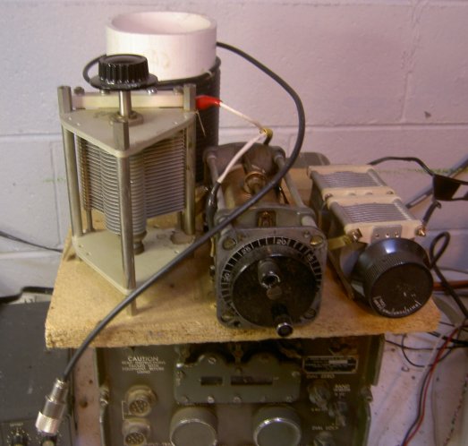 My QRO version
(left) has moderate-power components I've had on hand for
years,
with a "choke balun" on the input of about 25 feet of RG-58 coax wound
on a 5 inch PVC pipe. C1 is about 500 pF, C2 is 200 pF per section, and
the roller inductor is a GE component from a hamfest. After some years
of just having the components loose and clip-leaded together, I finally
mounted them on a piece of wood in November 1997, connected with straps
of brass stock from the local hobby shop.
My QRO version
(left) has moderate-power components I've had on hand for
years,
with a "choke balun" on the input of about 25 feet of RG-58 coax wound
on a 5 inch PVC pipe. C1 is about 500 pF, C2 is 200 pF per section, and
the roller inductor is a GE component from a hamfest. After some years
of just having the components loose and clip-leaded together, I finally
mounted them on a piece of wood in November 1997, connected with straps
of brass stock from the local hobby shop.
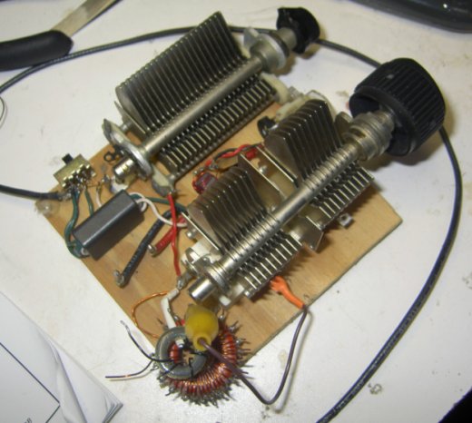 The QRP version
(right) uses smaller variable caps with narrower plate
spacing
-- about 350 pF for C1, 150 pF per section at C2. The inductor is a
T-106-2
toroid with lots of turns of #18 wire, with wire taps soldered on; a
clip
lead makes the necessary inductance adjustment. The input balun is
wound
on a BN-43-3312 Amidon two-hole ferrite core, 3 turns each for primary
and secondary. This handles the 50 watts of my Ten-Tec Argosy pretty
well
-- no arcing, and the balun seems to stay cool. The slide switch at
left permits bypassing the balun. Between the capacitors is a kludged
RF ammeter - a small ferrite toroid with a number of wire turns, a
diode/capacitor to rectify, and a meter to read the current.
The QRP version
(right) uses smaller variable caps with narrower plate
spacing
-- about 350 pF for C1, 150 pF per section at C2. The inductor is a
T-106-2
toroid with lots of turns of #18 wire, with wire taps soldered on; a
clip
lead makes the necessary inductance adjustment. The input balun is
wound
on a BN-43-3312 Amidon two-hole ferrite core, 3 turns each for primary
and secondary. This handles the 50 watts of my Ten-Tec Argosy pretty
well
-- no arcing, and the balun seems to stay cool. The slide switch at
left permits bypassing the balun. Between the capacitors is a kludged
RF ammeter - a small ferrite toroid with a number of wire turns, a
diode/capacitor to rectify, and a meter to read the current.
The big one matches just fine down to 160 meters with several turns
to spare. The little one is just fine too, and in a pinch serves as a
suitable
preselector for my DX440 receiver -- as you may know, such small
shortwave
portables need some preselection when used at night with an external
antenna
or they are just useless due to the intermodulation of the wide-open
front
end.
The original article cautions you to use tuner settings that use the
maximum possible capacitance for the greatest bandwidth and lowest
loss.
And sure enough, there is quite a range of inductance that you can use
as a starting point for a given frequency, the two C's being
subsequently
twiddled for a match. The lower the C (at higher L settings), the
sharper
the tuning feels, and sure enough, the bandwidth for a given SWR range
is narrower. Going from one end of a band to another, you usually just
have to retune L or C2 to fine-tune your match.
On reflection, you have an interesting practical laboratory exercise
in "bandwidth versus loaded Q." What's happening is that when you use
the
tuning options that make for higher C, you are actually loading the
tuned
circuit more heavily, thus decreasing the loaded Q. Just read those
sections
on bandpass filters in ARRL's "Solid State Design" or other references,
and it will make sense.
I find this and the Z-Match
tuner circuits to be useful because of their additional selectivity.
Being
a few miles from a 50 kW AM broadcaster, and a few other lower-power AM
stations that seem to ride in on my power lines, there are some
circumstances
where this helps clean up problems. Sure, the simple L network is
simplest,
and has the broadest SWR bandwidth. But the SPC seems to go down to 160
more easily than an L network with the same C1 and L as this tuner (the
big one at least) uses.
<>In closing, just one more true balanced tuner to mention... Rick
Measures,
AG6K, published "A Balanced Balanced Antenna Tuner" in Feb 1990 QST -
an
updated online version from the author is at http://www.somis.org/bbat.html.
I played with a version of this, and it worked well, but it doesn't
serve
to add any selectivity to your system (the only reason I have not used
it lately). It is a truly symmetrical network, as opposed to the above
network which simply floats with respect to ground.
In Oct. 2004 QST, Jack Belrose, VE2CV, again proposes simply putting
that balun ahead of a floating (but unbalanced) network, in this case
an L network. His view is that a true balanced situation results, and
one set of measurements backs this up.
Back to
main
page